 contact@nxhdmfg.com
 +86 352 5330772
 +86 180 3528 0246

The problem with specifying fasteners by price and dimension
Most fastener decisions get made on two variables: unit price and nominal dimension. Both are legitimate inputs. Neither predicts whether a bolt is still intact after ten years of service.
That outcome is determined upstream, in a chain of manufacturing decisions that rarely appears on a purchase order. The four variables below account for a large share of real-world fastener failures, and each one is controllable at the specification stage.
1. Thread geometry and fatigue fracture
Fatigue is the most common cause of fastener failure in service, and it is the one most often misdiagnosed as a material defect.
Fatigue damage accumulates under cyclic loading. It does not appear at assembly. It appears after a number of load cycles, at a location determined by stress concentration, and it gives almost no warning.
The geometry of the thread root is the controlling variable.
| Property | Cut thread | Rolled thread |
|---|---|---|
| Root profile | Sharp V, geometric stress raiser | Radiused transition, no sharp notch |
| Stress concentration | High | Lower by 30–50% |
| Fatigue strength | Reference baseline | 30–50% higher |
| Surface condition | Possible tool marks and burrs | Work-hardened, continuous fibre flow |
| Material utilisation | Lower | Higher |
| Subsequent tapping | Suitable | Poor — the formed profile tears |
The mechanism is straightforward. A cut thread removes material with a tool and leaves a sharp notch at the root. Under cyclic stress, a crack initiates at that notch and propagates until the section fails. A rolled thread forms the profile by displacing metal outward with hardened dies, producing a radiused root with no discontinuity in the fibre flow. The stress concentration is materially lower, and the fatigue limit rises accordingly.
Practical consequence: on any joint subject to vibration or cyclic loading — construction equipment, vehicles, rail, reciprocating machinery — specifying a rolled thread is one of the highest-value decisions available in the whole fastening spec. It costs almost nothing at the piece price and it changes the service life by a factor that dwarfs most other variables.
The question worth asking a supplier is short: are the threads rolled or cut?
Failure identification. Fatigue fracture surfaces show a distinct structure. A smooth, flat region marks the slow crack growth phase; a rough region of roughly 10–30% of the cross-section marks the final instantaneous fracture. A single-stage overload failure looks different — the whole section tears at once, with a uniformly coarse surface and no zoning. That distinction is the fastest way to separate fatigue from a bad batch.
2. Hydrogen embrittlement and the delayed fracture
This failure mode is the most dangerous, because it produces a joint that behaves normally at assembly and then fails without warning.
Mechanism. High-strength steel — generally property class 10.9 and above — absorbs hydrogen during acid pickling and electroplating. Under sustained tensile stress, hydrogen atoms migrate toward stress concentrations such as the thread root. At a critical concentration at the grain boundary, the material fractures.
Characteristics:
- Assembly and initial operation are entirely normal
- Failure occurs hours to several days after assembly
- The fracture surface shows little or no plastic deformation
- Darkening from hydrogen oxide is often present
Controls, in order of effectiveness:
- Prefer non-electrolytic coatings. Dacromet, zinc-aluminium and zinc-chromium conversion coatings deposit without generating hydrogen. This removes the risk rather than managing it.
- Specify documented embrittlement relief for any electroplated class 10.9 or higher part. The requirement is 4 hours or 48 hours depending on the applicable standard, and it is mandatory rather than optional. It must appear as a line on the purchase order.
- Control assembly stress. Over-torquing raises the stress that drives hydrogen migration.
- Use a hydrogen-sensitive grade designation where the standard offers one. A 10.9S grade is explicitly a hydrogen-sensitive class and is not interchangeable with a general-purpose 10.9.
A related mechanism appears in stainless steel. Austenitic stainless grades in chloride environments — coastal atmosphere, salt spray, chloride-containing cleaning agents — are susceptible to stress corrosion cracking. The failure is not uniform corrosion. It is intergranular cracking that propagates silently and then releases the joint without warning. Coastal applications need a molybdenum-bearing grade such as 316 rather than 304.
Testing. Where the application is safety-relevant, hydrogen embrittlement resistance is verified by the notched specimen test described in the relevant fastener standard. A material certificate alone does not address this failure mode.
3. Torque coefficient and preload error
Torque is the assembly-side variable, and the most frequently mishandled one.
The relationship is:
T = K × F × d
where T is tightening torque, K is the torque coefficient, F is the preload, and d is the nominal diameter.
K is not a constant. It aggregates thread friction, bearing face friction, and nut-to-washer contact friction. It ranges from 0.10 to 0.30 depending on condition.
| Condition | Typical K |
|---|---|
| New thread, dry, uncoated | 0.20 — the reference basis |
| New thread, lightly oiled | 0.18 |
| Reused thread, light surface rust | 0.22–0.25 |
| Thread lubricated | 0.10–0.12 |
| Dacromet or zinc plated | 0.12–0.15 |
| Hot-dip galvanised | 0.15–0.20 |
The consequential error is applying an unchanged torque value to a lubricated thread. If K falls from 0.20 to 0.10 while the specified torque stays the same, the delivered preload falls to approximately half of the intended value. The joint still appears tight. The operator still sees the torque wrench click. The design assumption simply no longer holds, and the joint is under-preloaded from the moment it is made.
The same reasoning applies in reverse. A reused or corroded thread pushes K upward, so a torque value calculated for new threads delivers a preload above the design intent — which, in a high-strength application, can mean thread yield during assembly.
Where lubrication is used, the correct approach is a measured K value, established by tension testing a sample from the actual production lot. Where it is not available, a K of 0.20 remains a defensible basis for dry, uncoated, new threads.
Reference tightening torque, calculated at K = 0.20 with preload at 70% of yield for a class 8.8 carbon steel fastener:
| Size | Design preload (N) | Tightening torque (N·m) |
|---|---|---|
| M8 | 5 500 | 9 |
| M10 | 9 200 | 18 |
| M12 | 16 300 | 39 |
| M16 | 37 000 | 118 |
| M20 | 70 500 | 282 |
| M24 | 122 000 | 586 |
| M30 | 235 000 | 1 410 |
Field practice frequently applies a factor of 1.1 to 1.3 above these figures. That margin is appropriate for class 8.8 and below, and is not recommended for class 10.9 and above, where over-torque causes thread yield and removes the ductility that higher-strength grades are meant to retain.
Tightening sequence. For flanged and multi-bolt joints, the pattern matters as much as the value. Tightening from the centre outward in a cross pattern, in three passes at 30%, 60% and the full final value, distributes the load evenly across the gasket or joint face. Sequential tightening from one side to the other concentrates the entire accumulated error on the final bolt, which is a routine cause of bolts breaking during assembly rather than in service.
Verification. On any joint where preload matters, a paint mark across the bolt head and nut provides a cheap and effective check. A mark that has moved indicates rotation, and a periodic sample of marked fasteners detects loosening long before it becomes a failure.
4. Galvanic corrosion between dissimilar metals
Two dissimilar metals in direct contact in a damp environment form a galvanic cell. The less noble metal corrodes, and the rate scales with the potential difference.
| Couple | Potential difference | Outcome |
|---|---|---|
| Zinc + aluminium | ~0.9 V | Aluminium corrodes rapidly |
| Zinc + copper or brass | ~0.8 V | Zinc coating consumed quickly |
| Carbon steel + 304 stainless | ~0.5 V | Carbon steel side corrodes |
| Zinc + 304 stainless | ~0.4 V | Zinc consumed faster |
| Aluminium + 304 stainless | ~0.1 V | Relatively safe |
Common failure pattern. An aluminium enclosure or rail is fastened with plated carbon steel bolts. In a damp environment the aluminium around each bolt hole corrodes, the hole enlarges, and the joint loosens. The bolts are often blamed, when the bolts were specified correctly and the pairing was not.
Mitigation, in order of preference:
- Match the materials. Carbon steel fasteners with carbon steel, stainless with stainless. This removes the cell entirely.
- Isolate dissimilar metals with a nylon washer or a non-conductive spacer at the interface.
- Coat the less noble metal with a barrier that prevents galvanic contact.
5. Property class and ductility reserve
Property classes are produced by quench and temper. Quenching produces hard martensite; tempering trades brittleness for toughness at a temperature that determines the class.
| Class | Tensile (MPa) | Yield (MPa) | Yield ratio | Character |
|---|---|---|---|---|
| 8.8 | 800 | 640 | 0.8 | Higher ductility reserve |
| 10.9 | 1000 | 900 | 0.9 | Higher strength, reduced reserve |
| 12.9 | 1200 | 1080 | 0.9 | Highest strength, least reserve |
The yield ratio is the number worth understanding. Class 8.8 sits at 0.8, class 10.9 at 0.9. A higher yield ratio means less plastic deformation is available between first yield and fracture. Under shock, impact, or severe vibration, that translates into a greater tendency toward brittle fracture rather than ductile yielding.
Higher is therefore not better. It is a deliberate trade of ductility for strength, and the correct class follows a calculated load case, not a general preference for stronger hardware. Selecting class 12.9 where the load case only requires 8.8 adds cost, adds assembly difficulty, and in a shock-loaded application adds a fracture risk that the lower class would not have had.
Putting it together
A workable specification sequence runs in this order:
- Calculate the load case. This determines the required class and the minimum preload.
- Decide the thread form. Cyclic or vibratory service means rolled threads.
- Select the coating from the service environment, then specify it as a measurable criterion — coating thickness or salt spray hours, per the applicable corrosion test standard. A descriptive term such as "corrosion resistant" is not a specification.
- Establish the K value for the actual assembly condition, dry or lubricated, and use the corresponding torque.
- Check the material pairing at every interface, and isolate where the pairing is mixed.
- Define the inspection documentation against the batch number, so that any individual part can be traced back to its material heat and its inspection record.
Each of these six decisions is made once, at the specification stage, and each one is far cheaper there than in a failure investigation.
About the process data behind this article
Each mechanism described above traces back to a specific manufacturing parameter: the roll angle and thread crest geometry that set the fatigue notch sensitivity, the plating immersion time and hydrogen bake that determine embrittlement risk, the K-factor variation across a batch of fasteners as received, and the galvanic series position of each coating against the base metal.
Standard and non-standard fasteners, special-shaped parts, riveting fasteners, self-tapping screws and lean castings are produced from two plants in northern China — Handan (Yongnian) for standard fastener volume production, and Datong for high-strength, special and custom parts. Over 1,000 product types, with management systems certified to ISO 9001, ISO 14001 and ISO 45001, and in-house dimensional, mechanical, coating and torque inspection with batch-level material traceability.
This is stated as process context for the technical content, not as a sales pitch. Where a figure above does not match your drawing or your service condition, the drawing wins.
NXHD Manufacturing (contact@nxhdmfg.com) is a precision fastener and custom metal parts manufacturer with dual production bases in Handan and Datong, China. We supply standard and non-standard fasteners to OEM customers across Europe, the Americas and Asia.
Frequently asked questions
What are the four most common fastener failure mechanisms?
Fatigue fracture driven by thread root geometry, hydrogen embrittlement introduced during pickling or electroplating, preload error caused by an incorrect torque coefficient assumption, and galvanic corrosion between dissimilar metals in a damp environment. All four are decided at the specification stage rather than in service.
How do I tell fatigue from hydrogen embrittlement on a broken part?
Fatigue shows distinct zones on the fracture surface — a smooth beach mark and a rough final rupture region — and it appears after hundreds or thousands of load cycles. Hydrogen embrittlement shows little or no plastic deformation, a clean break, often darkened by hydrogen oxide, and occurs hours to days after assembly. Neither should be cleaned or polished before examination, because that destroys the surface evidence.
What is the K factor in T = K × F × d?
K is the torque coefficient, also called the nut factor. It represents the combined friction of the threads, the bearing face and the nut-to-washer interface, and it ranges from 0.10 to 0.30 depending on surface condition. It is the single most misused variable in torque specification, because a lubricated thread with an unchanged torque setting roughly halves the delivered preload.
How do I prevent galvanic corrosion between dissimilar metals?
Use insulating washers or nylon spacers between dissimilar metals, or match the materials — carbon steel fasteners with carbon steel, stainless with stainless. Aluminium paired with 304 stainless is one of the safer combinations; zinc against aluminium or copper is among the worst, at roughly 0.8–0.9 V potential difference.
Can NXHD identify why a fastener failed?
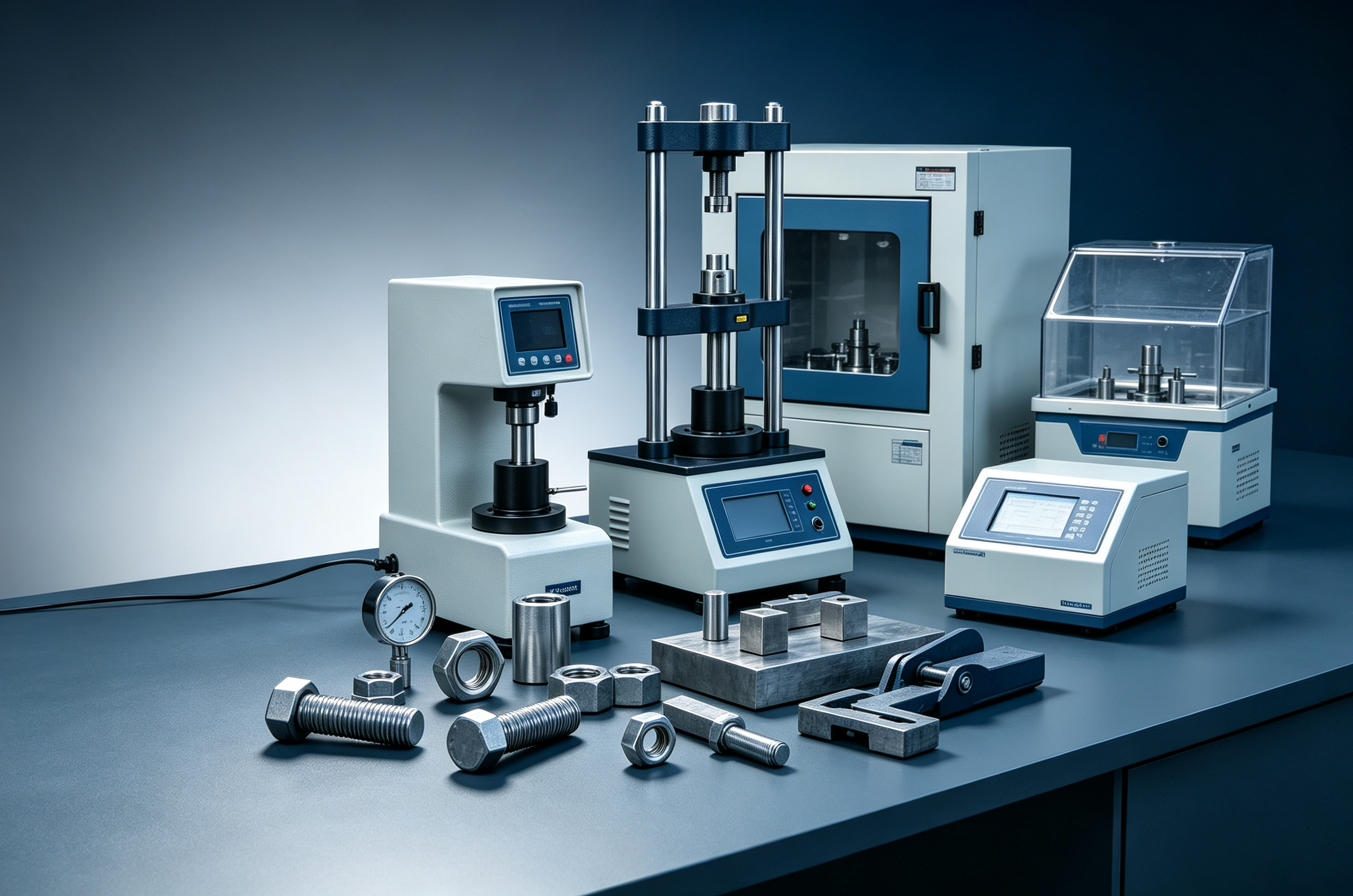
Yes. We photograph the part, its fracture surface and its installed position, retain the assembly (nut, washer and mating part) to establish preload and load direction, and record the service condition before metallographic, hardness and fracture-surface analysis is commissioned. In-house dimensional, mechanical, coating and torque inspection is available at both production bases.